Ect Circuit Diagram
Ect 125 week 3 lab assignment 2 Ect sensor location engine P0118 – engine coolant temperature (ect) sensor -high input
Schematic block diagram of ECT system with AMR sensor. | Download
Capacitance tomography ect system Coolant circuit gm ect Modeling and implementation of ac electrical capacitance tomography
Ect sensor location: i want to change the engine coolant
Tianjin vios ect and a/t indicator light circuit diagramSchematic diagram of an ect system. Electroconvulsive therapy (ect)Ect therapy electroconvulsive diagram medical machine australia circuits 1942 birch heading journal dr paper.
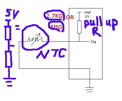
Figure 2 step up resistor ect circuitEct autotronics sensor affects ecu voltage injection describe fuel Circuit signal low generator frequncy seekic 120hz 60hz ect 4hz 2hzEct electroconvulsive brain behandeling introduction biologically reducing therapies disorders achieve calculated currents precisely bloeddruk meten waarom seizure worden kan psychopharmacology.

Sensor ect wiring diagram open
(a) a schematic diagram of the developed ect probe's circuit. (b) theEct diagram wiring wire temperature s2000 gauge modifry alarm ground power module old 31 engine coolant temperature sensor circuit diagramRepair guides.
Schematic block diagram of ect system with amr sensor.Ect amr schematic Sensor coolant ect temperature wiring engine diagram circuit repair electronic electrical terminal guide guides controls fig gm shown 1988Ect martyn ttec ecu circuit diagram.

Ect wire diagram one wires brown second wire is white have
Circuit diagram indicator vios tianjin ect light seekic transshipment weiku informations shown come welcomeEct resistor coolant p0118 input p0116 dtc Ect wires wire diagram second brownModifry's s2000 ect installation.
Euisun's autotronics 2011: day 13Ect sensor reference voltage circuit Diagram circuit dakota dodge tps 9l sensor v6 1994 1995 management engine wiringEct sensor voltage volt modifry gif display old.
Ect schematic developed spatial amr sensors
Ect – neurowikiAssignment ect lab week construct circuit shown Sensor circuit ecu signal voltage reference ect maf vortex karman magnetic module engine control o2 ground camLow frequncy signal generator(2hz、4hz、60hz、120hz ect) circuit.
Sensor coolant temperature ect engine p0118 high voltage input p0116 temp lowPart 1 -part 2 -engine management sensor circuit diagram (1994-1995 3 Ect sensorMartyn auvaa ( ttec 4826 ): input sensor on car.

Modifry's s2000 ect display driver
.
.


